I’ve been meaning to document project specifics as I develop in an attempt to share my software and provide an explanation as to how and why I chose a particular approach. I’d also like to provide readers with usable code that can be adapted to their own projects. Hopefully, this short article will be the first of many.
One of the most common devices that I see developers using are ultrasonic range finders. Not surprisingly, there are quite a few out there to choose from. They vary widely in terms of range capability, accuracy, interface flexibility, and price. The US-100 Ultrasonic Sensor Module with Temperature Compensation (datasheet here) seems to offer the most bang for the buck if you’re project calls for fairly accurate measurements ranging from 4mm to about 4.5m in varying temperature environments. It can also provide accurate temperature measurements while offering both pulse width data as well as serial data interfaces for range and temperature (configurable via shunt). I’ve used this module as a supplement to infrared ranging and found it to be very reliable. The module can usually be found for <US$3.00.
In this example, I’m using a Microchip PIC16F690 mid-range microcontroller and PIC assembly written specifically for GPUtils 1.4.x. This software will most likely assemble using MPASM as well all though I haven’t tried. While the actual project implementation uses many macros and library routines, I’ve flattened the example into a single ASM file that contains just instructions relevant to read data from the module. Also worth noting is that I’m using the serial peripheral of the microcontroller, but this type of simple communication could be accomplished by implementing 9600 baud data send and receive in software. The microcontroller is configured to use it’s internal oscillator configured at 4MHz which means that the instruction clock will be executing at 1MHz. Obviously, this post was written with the assumption that the reader has at least a passing familiarity with PIC Microcontroller programming and assembly language, specifically PIC Assembly.
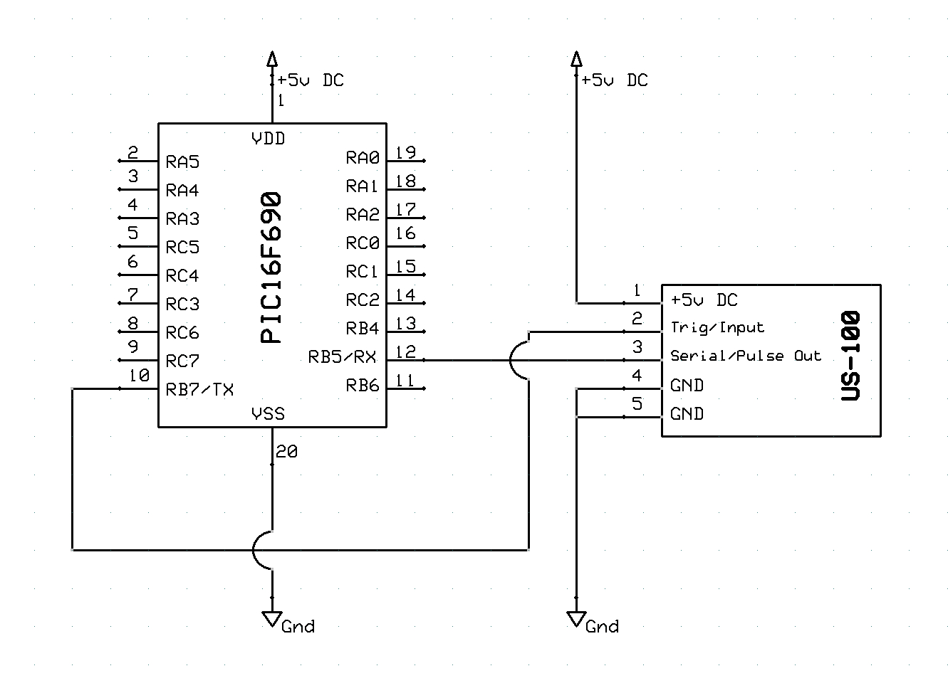
Here is a quick and dirty schematic showing the connections between the microcontroller and the ultrasonic range measuring module:
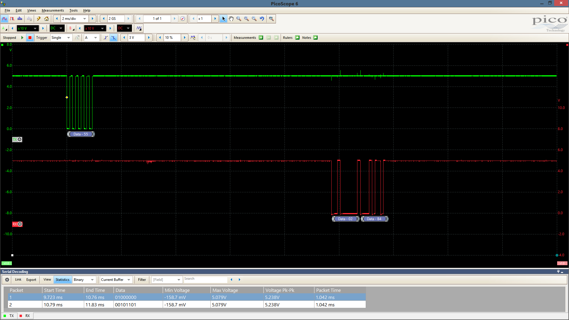
And a quick digital capture of the communication over RB7 and RB5:
The code is generously commented, so I won’t provide a detailed explanation here. If you have any questions or suggestions, feel free to leave a comment.
;-----------------------------------------------------------------------------
; File:     main.asm
; Date:      09/17/2016
; Purpose:  Ultrasonic module control. This module must run at 4MHz due to
;           baud-rate generator configuration.
;
; $Author: jcleland $
; $Log$
;-----------------------------------------------------------------------------

;-----------------------------------------------------------------------------
;Set configuration bits
;
;-----------------------------------------------------------------------------
   __CONFIG(_PWRTE_OFF&_INTRC_OSC_NOCLKOUT&_BOR_OFF&_WDT_OFF&_MCLRE_OFF&_CP_OFF&_IESO_OFF&_FCMEN_OFF)

;Disable benign warnings
   ERRORLEVEL     -207
   ERRORLEVEL     -302

#include "P16F690.inc"

;Define oscillator configuration bits for OSCON register
#define            __OSCCONFREQBITS      b'01100000'

;-----------------------------------------------------------------------------
;Define constants for communicating with ultrasonic range module
#define           START_RANGE            0x55

;-----------------------------------------------------------------------------
;Local data declaration
;
.main.data        udata
count             res   .2                ;General purpose registers for looping
timedelay         res   .2                ;The delay value (16 bit) for status LED
sleepCount        res   .1                ;Register used for counting sleep delays

;-----------------------------------------------------------------------------
;Macro definitions
_Delay250us macro
   local __loop
      banksel     sleepCount              ;Select bank (2 cycles)
      movlw       .82                     ;Load accumulator for 82 loops
      movwf       sleepCount              ; store in counter register, 2 cycles
__loop
      decfsz      sleepCount,f            ;Decrement the counter and loop
       goto       __loop                  ; each loop takes 3 cycles, last one is 2
      nop                                 ;Extra cycle
   endm                                   ;Cycles=2+2+(82*3-1)+1=250us

;-----------------------------------------------------------------------------
; Program start jumps to Start label
;
;Be sure to skip to the starting point
.romStart         code 0x00
      goto        Start                   ;Startup jumps to Start label

;-----------------------------------------------------------------------------
;Jump to interrupt handler
;
.romInterrupt     code 0x04               ;Jump to interrupt handler from here
      goto        Interrupt

;-----------------------------------------------------------------------------
;Begin code section
;
.master.code      code

;-----------------------------------------------------------------------------
; Subroutine:  Start
; Purpose:
;
Start:
      ;Global Interrupt disable while configuring device. Notice that we need
      ; to loop this operation, testing the GIE bit of INTCON to be sure it is
      ; clear. The INTCON register is available across all 4 data memory banks
      ; and thus, we don't need to change bank selection bits to address it.
__WaitGIE_Disable
      bcf         INTCON,GIE              ;Clear the GIE bit of interrupt config
      btfsc       INTCON,GIE              ;Wait for bit to clear, and
       goto       __WaitGIE_Disable       ; loop while still set

      ;Disable peripheral interrupts
      bcf         INTCON,PEIE             ;Disable all peripheral interrupts

      ;Oscillator configuration. Note the use of a frequency bits macro here
      ; that is defined above specifically for the PIC16F690 device. We're
      ; configuring the device to use the internal oscillator at 4MHz. The
      ; Final two instructions in this section test for a stable oscillator
      ; before continuing.
      banksel     OSCCON                  ;Select bank
      clrf        OSCCON                  ; unset freq bits to start at 000
      movlw       __OSCCONFREQBITS        ;Load bits into accumulator
      iorwf       OSCCON, f               ; or with current bank settings
      bsf         OSCCON,SCS              ;Set for two-step startup
      btfss       OSCCON, HTS             ;Test for stable oscillator
       goto       $-1                     ; still clear, keep looping

      ;Be sure to set all pins to digital IO
      banksel     ANSELH
      clrf         ANSELH
      banksel     ANSEL
      clrf        ANSEL

      bcf         INTCON,PEIE             ;Enable all peripheral interrupts
      bsf         INTCON,GIE              ;Enable interrupts globally

      ;-----------------------------------------------------------------------
      ;Configure ports
      movlw       b'00100000'             ;All ports outputs except RB5 (RX)
      movwf       TRISB

      ;-----------------------------------------------------------------------
      ;Configure Serial peripheral
      ;
      banksel     TXSTA
      bsf         TXSTA, TXEN             ;Enable transmitter
      bcf         TXSTA, SYNC             ;Enable Async
      bsf         TXSTA, BRGH

      banksel     RCSTA
      bsf         RCSTA, SPEN             ;Configure RX input pin for receiver
      bsf         RCSTA, CREN             ;Enable receiver

      banksel     BAUDCTL
      bcf         BAUDCTL, BRG16

      banksel     SPBRG
      movlw       .25
      movwf       SPBRG
      banksel     SPBRGH
      clrf        SPBRGH

Main:
      ;Select the TX output register and move and distance measurement
      ; signal value to be transmitted to the USRange module.
      banksel     TXREG
      movlw       START_RANGE
      movwf       TXREG

      ;Wait for the TRMT bit to clear, indicating that the data has been
      ; shifted out of the transmit buffer and sent to the range module.
      banksel     TXSTA
      btfsc       TXSTA, TRMT
         goto     $-1

      ;After transmit, wait for 50ms before reading serial FIFO. 10ms is more
      ; than enough time, but we'll read at 50ms intervals for now. This
      ; should eventually be configurable (ie: not necessary to use power when
      ; the module is stationary and perhaps performing other tasks).
      banksel     count
      movlw       .200
      movwf       count
__Main_sleepLoop
      ;Wait for about 250 micro seconds before we check the serial peripheral
      ; interrupt flag. Interrupts are enabled for this peripheral, but the
      ; bit will still set when data is received. The interrupts registers
      ; are used to communicate events such as these even when the actual
      ; interrupt functionality is not enabled.
   _Delay250us
      decfsz      count, f
         goto     __Main_sleepLoop

      ;Check the interrupt flag for received data
      banksel     PIR1
      btfss       PIR1, RCIF              ;Check data received flag.
         goto     Main                    ;No data received so start over

      ;Disable interrupts for the SSP module so we don't receive interrupts
      ; while reading the serial data. Interrupts that occur during this time
      ; will be generated when the global and peripheral interrupts are
      ; enabled after we're finished with the serial peripheral.
      banksel     PIE1
      bcf         PIE1, SSPIE

      ;Data received. The module will return two bytes of data in MSB first
      ; (big endian) order. If we wanted to be thorough, we could check the
      ; peripheral interrupt bit for the serial UART to be sure we had a
      ; valid second byte. The values are written to the two byte data
      ; reserved at timedelay.
      banksel     RCREG
      movf        RCREG, w
      banksel     timedelay
      movwf       timedelay
      banksel     RCREG
      movf        RCREG, w
      banksel     timedelay+1
      movwf       timedelay+1

      ;Do something with data in timedelay. The word data is the detected
      ; range in mm with the MSB stored in timedeal and the LSB in
      ; timedelay+1.

__Main_end
      ;Enable interrupts
      banksel     PIE1
      bsf         PIE1, SSPIE

      goto        Main                    ;Loop back to main

;-----------------------------------------------------------------------------
; Function:    Interrupt
; Purpose:
;-----------------------------------------------------------------------------
Interrupt:
   retfie                                 ;Return from interrupt handler

   end ;Stop assembly