One of the first things that do in software when beginning a new implementation that utilizes the internal oscillator of a PIC micro device is check the accuracy of the oscillator. Once I’m satisfied that the oscillator frequency is as close to spec as possible, I’ll usually write this to EEPROM data to be read and applied on startup. The internal oscillator can be inaccurate by a significant margin which may lead to random errors in timing critical functions as well as peripherals that rely on FOSC such as the USART peripheral which may generate intermittent framing errors that are hard to track down if you’re trusting the internal oscillator without calibration. Additionally, if the internal oscillator runs fast, for example, and you’re trying to maximize performance of a serial bus by following minimum spec state times and transitions you may find that you’re delays are, in fact, out of spec by a few nanoseconds which can cause intermittent problems.
Here’s an example of what I might do with a blank assembly file before I even think about actual program logic:
Start:
      ;Oscillator configuration
      banksel     OSCTUNE
      movlw       b'01000000'
      movwf       OSCTUNE

      banksel     OSCCON
      movlw       b'01110000'
      movwf       OSCCON

      banksel     TRISA
      movlw       b'00000000'
      movwf       TRISA

      banksel     PORTA
Main:
      bsf         PORTA, 0
      nop
      nop
      nop
      bcf         PORTA, 0
      nop
      goto        Main                 ;Loop back to main
Notice that line 4 contains the configuration for the OSCTUNE register. OSCTUNE:6 is a PLL enable bit, the actual tuning bits are the least significant 5 (OSCTUNE:0-:4). When these bits are all clear, the tuning for the internal oscillator is considered to be ‘Center’. The least significant 4 bits are tuning values while OSCTUNE:5 indicates whether you are adjusting the frequency up or down (clear is up, 1 is down). Note that tuning down starts at 11111 and is lowest at 10000. Adjusting the oscillator frequency up starts at 00001 and is fastest at 11111.
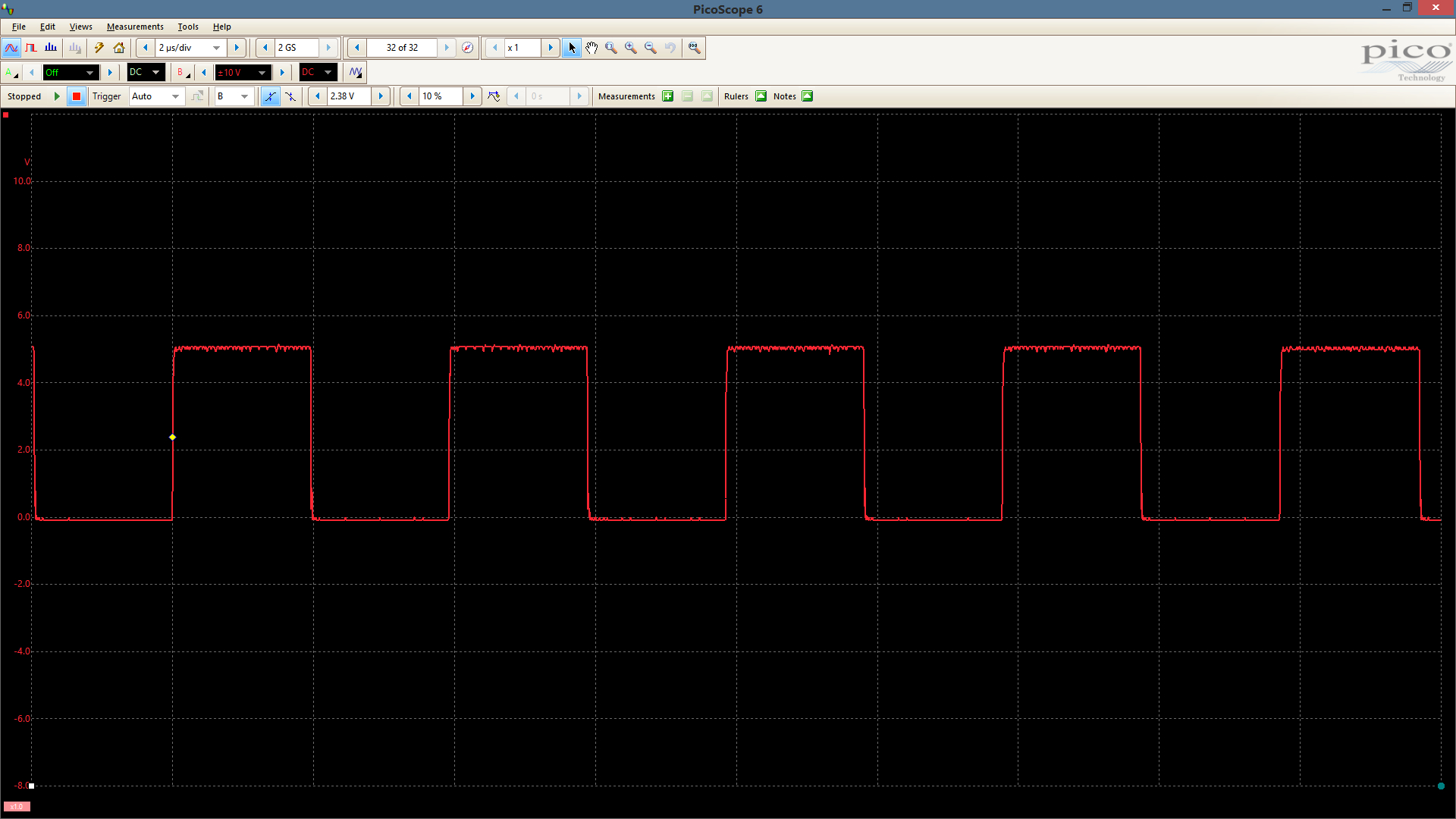
Testing this logic on a PIC18f2620 with the internal oscillator configured for 8MHz (as seen in the example above), I can evaluate the accuracy using the main loop. The logic in the main loop wastes 4 instruction cycles per state change on PORTA:0. I usually pull this pin high and may use it to drive an LED although at this frequency you will not see any change in the LED state 🙂 So, at 8MHz, I’m executing one instruction every 500ns. Two instructions takes 1us and 4 instructions (code) should take 2us. Here is a screenshot of my untuned oscillator with the scope horizontal scale set to 2us per division. Ideally, the trace should align perfectly to the scale divisions:

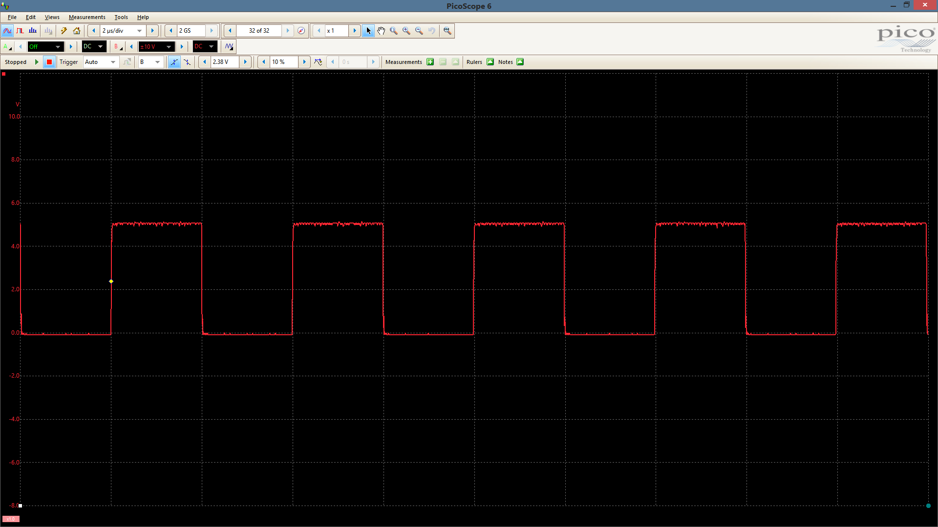
But it doesn’t. In fact, it’s way off. So far off that I’m 2us behind in100us. That’s a 2% error! Here is the same device with the oscillator tuned as close as possible to 8MHz:

Notice that the internal oscillator is now very close to dead-on.
I totally agree James, hadn’t thought about it before, when using external crystals or oscillators. Recently, however, I’ve switched a project to using a total of 5 PICs from 2 families (18LF & 12LF) where high speed communication is key. I noticed that there were timing errors on the outputs between the 4 PICs producing the required output, definitely visible at lower frequencies. Plus, it was noted that communications required longer delays than before. In order to tighten up communication and produce the same output needed it was clear that some sort of calibration of the internal oscillators would be required. I had not realized that there was such a range when coming from the factory. Application notes on the topic of auto-calibration have helped greatly and now have a tightly tuned system. Very nice write-up and great visuals. Thanks for your contribution!