Updated: For a working example, please read this post next. It provides schematic and software that will display the output of the Maxim DS1620 on any Hitachi 44780-compatible LCD.
I was in the shop the other day, putting some FETs away and labeling drawers when I came across a drawer full of DS1620s. I have a bunch of them, I don’t know why. Anyway, I thought it would be fun to see what kind of effort it took to interface this device using, of course, PIC assembly language and a PIC16f690 midrange device.
The DS1620 is a digital thermometer and thermostat. if you wanted to build your own home HVAC thermostat, you might choose to use this device. It allows the developer to set high and low temperature limits that, when reached, will cause one of two limit pins on the device to go high. The usefulness should be obvious. More simple applications allow for reading of temperature in either a continuous conversion mode or by triggering a start and stop conversion, followed by a temperature read.
The CPU communicates with the DS1620 using a 3-wire protocol. Two lines are used as clock and data, while a third reset line is used to initiate and terminate communication “sessions”. The data sheet for the DS1620 is not extremely clear regarding when the bus needs to be reset, which is achieved by driving the reset pin on the device low. My experimentation suggests that a bus reset is required following every logical transaction. Some transactions are one-way and don’t require a response. Bus reset. Others require a request (read temperature) and a reply (9-bit temperature value). Bus reset. You get the idea.
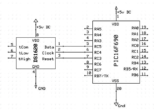
So, Wiring is pretty straight forward as is indicated below by my 5-minute schematic:
A trace of the activity on the data and clock pins can be seen below. I’ll break each transaction down briefly and explain what’s going on:
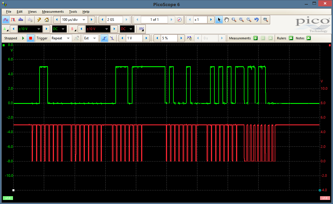
The green trace is the data pin activity, the red is the clock pin. The reset is not shown, but is used to trigger the oscilloscope, as you can see by the tool bar. Let’s see what’s going on here in terms of transactions.
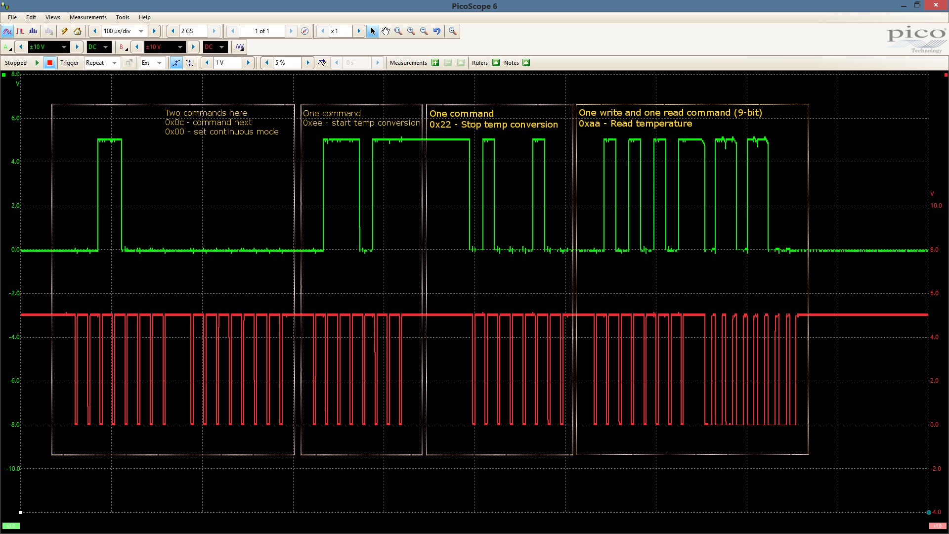
I’ve drawn boxes around each communication “transaction” that is taking place. Note that the first three are write-only: There is no reply from the DS1620. I know the image is a little hard to read but it can be zoomed by clicking. It’s important to note that there is a bus reset in between each box.
The first communication consists of two 8-bit messages: 0x0C and 0x00. These two mean “I’m sending a command” and “Operate in continuous mode”, respectively. The second box surrounds a request to start a temperature conversion (0xEE). There is a 60us delay between the start conversion and the third box which tells the device to stop the current conversion (0x22). The fourth box can be divided into two parts, the second of which we’ll look at more closely in a minute. The communication contained herein is a command 0xAA (read current converted temperature) and the subsequent, 9-bit reply in LSb order meaning that we’re getting the information backwards :).
For a closer look at what is being sent back, let’s analyze the receive portion of the last transaction:
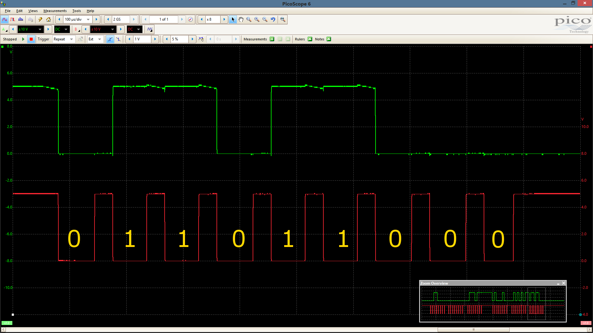
I’ve noted in the clock trace the value of the data pin. As mentioned above, this is receive LSb first and there are 9 bits. Basically, the LSb is a 0.5 degree indicator, so if we want to actual value we need to first reverse this bits and then shift that one off unless we want to save the precision. That would give us b’00011011′ which equals decimal 27 or 27 degrees C which is a toasty 80.6F.
I hope this explanation made at least a little bit of sense, but I’m sure the actual code can fill in what I failed to convey 🙂 A zipped download is available below. Additionally, the complete source listing for each file can be found below. Note that the makefile is only included in the zip archive and requires a GPUtils installation. If you have trouble assembling the source, check to be sure that you’re executable paths have the correct separator if you are using Windows.
Download makefile and asm source for this project.
;-----------------------------------------------------------------------------
; File:     main.asm
; Date:		01/30/2017
; Purpose:  This module programs and reads temperature from a maxim DS1620
;           thermostat temperature device.
;
; $Author: jcleland $
; $Log$
;-----------------------------------------------------------------------------

;-----------------------------------------------------------------------------
; This application assumes the following pinouts for P16F690
;
;                 VDD    -|----|-    VSS
;                 RA5    -|    |-    RA0
;                 RA4    -|    |-    RA1
;                 RA3    -|    |-    RA2
;          Data   RC5    -|    |-    RC0
;         Clock   RC4    -|    |-    RC1
;         Reset   RC3    -|    |-    RC2
;                 RC6    -|    |-    RB4
;                 RC7    -|    |-    RB5
;                 RB7    -|----|-    RB6
;
;-----------------------------------------------------------------------------

;-----------------------------------------------------------------------------
;Set configuration bits
;
;-----------------------------------------------------------------------------
   __CONFIG(_PWRTE_OFF&_INTRC_OSC_NOCLKOUT&_BOR_OFF&_WDT_OFF&_MCLRE_OFF&_CP_OFF&_IESO_OFF&_FCMEN_OFF)

;Disable benign warnings
   ERRORLEVEL     -207
   ERRORLEVEL     -302

;Include processor header
#include "P16F690.inc"

;Define oscillator configuration bits for OSCON register
#define            __OSCCONFREQBITS      b'01110000'

;-----------------------------------------------------------------------------
;Local data declaration
;
.main.data        udata
loop              res   .1                ;General use register

;-----------------------------------------------------------------------------
;Include local headers
#include "util.inc"
#include "ds1620.inc"

;-----------------------------------------------------------------------------
; Program start jumps to Start label
;
;Be sure to skip to the starting point
.romStart         code 0x00
      goto        Start                   ;Startup jumps to Start label

;-----------------------------------------------------------------------------
;Jump to interrupt handler
;
.romInterrupt     code 0x04               ;Jump to interrupt handler from here
      goto        Interrupt

;-----------------------------------------------------------------------------
;Begin code section
;
.master.code      code

;-----------------------------------------------------------------------------
; Subroutine:  Start
; Purpose:
;
Start:
      ;Global Interrupt disable while configuring device. Notice that we need
      ; to loop this operation, testing the GIE bit of INTCON to be sure it is
      ; clear. The INTCON register is available across all 4 data memory banks
      ; and thus, we don't need to change bank selection bits to address it.
__WaitGIE_Disable
      bcf         INTCON,GIE              ;Clear the GIE bit of interrupt config
      btfsc       INTCON,GIE              ;Wait for bit to clear, and
       goto       __WaitGIE_Disable       ; loop while still set

      ;Disable peripheral interrupts
      bcf         INTCON,PEIE             ;Disable all peripheral interrupts

      ;Oscillator configuration. Note the use of a frequency bits macro here
      ; that is defined above specifically for the PIC16F690 device. We're
      ; configuring the device to use the internal oscillator at 4MHz. The
      ; Final two instructions in this section test for a stable oscillator
      ; before continuing.
      banksel     OSCCON                  ;Select bank
      clrf        OSCCON                  ; unset freq bits to start at 000
      movlw       __OSCCONFREQBITS        ;Load bits into accumulator
      iorwf       OSCCON, f               ; or with current bank settings
      bsf         OSCCON,SCS              ;Set for two-step startup
      bcf         OSCCON, 3

      banksel     OSCTUNE
      movlw       b'00000000'
      movwf       OSCTUNE

      btfss       OSCCON, HTS             ;Test for stable oscillator
       goto       $-1                     ; still clear, keep looping

      bsf         INTCON,PEIE             ;Enable all peripheral interrupts
      bsf         INTCON,GIE              ;Enable interrupts globally

      ;Be sure to set all pins to digital IO
      banksel     ANSELH
      clrf        ANSELH
      banksel     ANSEL
      clrf        ANSEL

      ;-----------------------------------------------------------------------
      ;Configure ports
      banksel     TRISC                   ;Select tristate bank
      movlw       b'00000000'             ;Set all port C pins to outputs
      movwf       TRISC

   __DS1620Init                           ;Initialize the DS1620

Main:
   __Delay500us                           ;Delay in reset for 500us each cycle

      ;This block of code issues two command bytes: The first indicates that
      ; there is a configuration command to follow and the second tells the
      ; DS1620 to operate in continuous conversion mode.
      banksel     ds1620cmd
      movlw       0x0c
      movwf       ds1620cmd
   __Delay10us
   __DS1620WriteCommand

      banksel     ds1620cmd
      movlw       0x00
      movwf       ds1620cmd
   __Delay10us
   __DS1620WriteCommand

   __DS1620BusReset

      ;The next pair of commands are seperated by a 60 microsecond delay. The
      ; first tells the processor to begin temperature conversion and the
      ; second tells it to stop. We stop conversion before reading the temp
      ; value.
      banksel     ds1620cmd
      movlw       0xee
      movwf       ds1620cmd
   __Delay10us
   __DS1620WriteCommand

      banksel     ds1620cmd
      movlw       0x22
      movwf       ds1620cmd
   __Delay60us
   __DS1620WriteCommand

   __DS1620BusReset

      ;Finally, we issue a 0xAA (read temperature) instruction, then read the
      ; 9-bit result from the device.
      banksel     ds1620cmd
      movlw       0xaa
      movwf       ds1620cmd
   __Delay10us
   __DS1620WriteCommand

   __Delay10us
   __DS1620ReadWordData

   __DS1620BusReset
      goto        Main                    ;Back to main, start over

;-----------------------------------------------------------------------------
; Function:    Interrupt
; Purpose:
;-----------------------------------------------------------------------------
Interrupt:
   retfie                                 ;Return from interrupt handler

   end ;Stop assembly
;-----------------------------------------------------------------------------
; File:     util.inc
; Date:		01/30/2017
; Purpose:  Contains utility functions for delays, etc
;
; $Author: jcleland $
;-----------------------------------------------------------------------------

;Include once
#ifndef		__UTIL_INC
   #define  __UTIL_INC

;-----------------------------------------------------------------------------
;Local data declaration
;
.util.data        udata
_sleep_time_us    res   .2                ;General use register

;-----------------------------------------------------------------------------
; Macro:    __TuneOscillator
; Purpose:  This macro produces a pulse on the specified pin at 4 instruction
;				cycles, useful for tuning the internal oscillator.
;-----------------------------------------------------------------------------
__TuneOscillator macro port, pin
   local __label1
      banksel		port
__label1
      bsf			port, pin
      nop
      nop
      nop
      bcf			port, pin
      nop
      goto			__label1
   endm

;-----------------------------------------------------------------------------
; Macro:    __Delay2us
; Purpose:  Wastes 2us of time
; Accuracy: Dead-on
;-----------------------------------------------------------------------------
__Delay2us macro
   local __label1
   local __label2
      goto __label1
__label1
      goto __label2
__label2
   endm

;-----------------------------------------------------------------------------
; Macro:    _Delay4us
; Purpose:  Wastes 4us of time
; Accuracy: Dead-on
;-----------------------------------------------------------------------------
__Delay4us macro
     __Delay2us
     __Delay2us
   endm

;-----------------------------------------------------------------------------
; Macro:    __Delay10us
; Purpose:  Wastes 10us of time
; Accuracy: Dead-on
;-----------------------------------------------------------------------------
__Delay10us macro
   local __loop
      banksel     _sleep_time_us    ;Select bank (2 cycles)
      movlw       .5                ;Load accumulator for 5 loops
      movwf       _sleep_time_us    ; store in counter register, 2 cycles
__loop
      decfsz      _sleep_time_us,f  ;Decrement the counter and loop
       goto       __loop            ; each loop takes 3 cycles, last one is 2
      nop                           ;Extra cycle
      nop                           ;Extra cycle
   endm                             ;Cycles=2+2+(5*3-1)+2=20=10us

;-----------------------------------------------------------------------------
; Macro:    __Delay60us
; Purpose:  Wastes 60us of time
; Accuracy: Dead-on
;-----------------------------------------------------------------------------
__Delay60us macro
   local __loop
      banksel     _sleep_time_us    ;Select bank (2 cycles)
      movlw       .39               ;Load accumulator with loop count
      movwf       _sleep_time_us    ; store in counter register (2 cycles)
__loop
      decfsz      _sleep_time_us,f  ;Decrement the counter and loop
       goto       __loop            ; each loop takes 3 cycles, last one is 2
   endm                             ;Cycles=2+2+(39*3-1)=120=60us

;-----------------------------------------------------------------------------
; Macro:    __Delay500us
; Purpose:  Wastes 500us of time
; Accuracy: Dead-on
;-----------------------------------------------------------------------------
__Delay500us macro
   local __loop
      banksel     _sleep_time_us    ;Select bank (2 cycles)
      movlw       .249              ;Load accumulator for 249 loops
      movwf       _sleep_time_us    ; store in counter register, 2 cycles
__loop
      nop                           ;Waste cycle
      decfsz      _sleep_time_us,f  ;Decrement the counter and loop
       goto       __loop            ; each loop takes 3 cycles, last one is 2
      nop                           ;Extra cycle
   endm                             ;Cycles=2+2+(249*4-1)+1=1000=500us

;Include once
#endif
;-----------------------------------------------------------------------------
; File:     ds1620.inc
; Date:		01/30/2017
; Purpose:
;
; $Author: jcleland $
;-----------------------------------------------------------------------------

;Include once
#ifndef		__DS1620_INC
   #define	__DS1620.INC

;Include util for delays
#include "util.inc"

;-----------------------------------------------------------------------------
;Constants declaration
;
DSPORT				equ	PORTC
DSTRIS				equ	(DSPORT|0x80)
DSRST					equ	3
DSCLK					equ	4
DSDAT					equ	5

;-----------------------------------------------------------------------------
;Local data declaration
;
.ds1620.data      udata
ds1620loop			res	.2						;Loop counter register
ds1620cmd			res	.1						;Command data register
ds1620data			res	.2						;Data register

;-----------------------------------------------------------------------------
; Macro:    __DS1620Init
; Purpose:  Configures the device port and sets the 3-wire bus in reset
;-----------------------------------------------------------------------------
__DS1620Init macro
      ;Select the tristate register and configure all 3-wire pins as outputs
      banksel		DSTRIS
      movlw			(1<<DSRST) & (1<<DSCLK) & (1<<DSDAT)
      iorwf			DSTRIS, f

      ;Set the initial state for the bus: reset low and clock high. We don't
      ; care how the data pin in configured at this point
      banksel		DSPORT
      bcf			DSPORT,DSRST
   __Delay2us
      bsf			DSPORT,DSCLK
   __Delay2us
   endm
;-----------------------------------------------------------------------------
; Macro:    __DS1620BusReset
; Purpose:  Resets the 3-wire bus state and terminates any active transaction
;				with the device. The reset line is left low, clock is left high,
;				the data line is unchanged.
;-----------------------------------------------------------------------------
__DS1620BusReset macro
      ;Reset the initial state for the bus: reset low and clock high. We don't
      ; care how the data pin in configured.
      banksel		DSPORT
      bcf			DSPORT,DSRST
   __Delay2us
      bsf			DSPORT,DSCLK
   __Delay2us
   endm

;-----------------------------------------------------------------------------
; Macro:    __DS1620WriteCommand
; Purpose:  This macro writes the command data in the ds1620cmd file register
;				to the device. It does not reset the bus prior to sending the
;				command.
;-----------------------------------------------------------------------------
__DS1620WriteCommand macro
   local __bitLoop, __dataLow, __dataHigh, __clockData

      ;Load the loop register for 8 bits to send
      banksel		ds1620loop
      movlw			.8
      movwf			ds1620loop

      ;Select the port bank and drive the reset pin high to begin
      ; communication
      banksel		DSPORT
      bsf			DSPORT,DSRST
   __Delay2us

__bitLoop
      ;Send the command data LSb first, branch on bit 0. We'll shift through
      ; each bit so what is bit 1 will be bit 0 on the next iteration. We'll
      ; do this 8 times.
      banksel		ds1620cmd
      btfss			ds1620cmd,0
         goto		__dataLow
      goto			__dataHigh

__dataLow
      banksel		DSPORT
      bcf			DSPORT,DSDAT
      goto			__clockData

__dataHigh
      banksel		DSPORT
      bsf			DSPORT,DSDAT

__clockData
   __Delay2us

      ;Now that the data pin is set to 0 or 1 for the current bit, strobe the
      ; clock line for 2 microseconds, allowing the device to read the current
      ; data bit.
      bcf			DSPORT,DSCLK
   __Delay2us
      bsf			DSPORT,DSCLK

      ;Rotate the command byte right, shifting bit 0 into the carry flag. All
      ; bits move down one position so bit 1 is now bit 0 and soforth.
      banksel		ds1620cmd
      rrf			ds1620cmd, f

      ;Check the counter to see if we've sent all 8 bits. If not, loop back
      ; to __bitLoop and send the next bit in the command byte.
      banksel		ds1620loop
      decfsz		ds1620loop, f
         goto		__bitLoop
   endm

;-----------------------------------------------------------------------------
; Macro:    __DS1620ReadWordData
; Purpose:  This macro reads word data from the device into the ds1620data
;				file register. The data is read LSB first, but stored MSB
;-----------------------------------------------------------------------------
__DS1620ReadWordData macro
   local __bitLoop, __dataLow, __dataHigh, __byteRead

      banksel		ds1620loop					;Select loop buffer bank
      movlw			.8								;Load for 8 bit read in low byte
      movwf			ds1620loop					;

      banksel		ds1620data					;Select data bank
      clrf			ds1620data					;Clear the output register word
      clrf			ds1620data+1				; bytes

      movlw			ds1620data+1				;Load the address of data buffer
      movwf			FSR							; into FSR for indirect addressing

      banksel		DSTRIS						;Select tristate register bank
      bsf			DSTRIS,DSDAT				; and switch data pin to input

   __Delay2us

__bitLoop
      banksel		DSPORT						;Clock low to read first byte
      bcf			DSPORT,DSCLK				;Set clock low to read bit
   __Delay2us
      btfss			DSPORT,DSDAT
         goto		__dataLow
      goto			__dataHigh

__dataLow
      bcf			STATUS, C					;Bit is low, clear carry and
      rlf			INDF, f						; rotate carry flag into data
      goto			__byteRead

__dataHigh
      bsf			STATUS, C					;Bit is low, clear carry and
      rlf			INDF, f						; rotate carry flag into data

__byteRead
   __Delay2us
      bsf			DSPORT,DSCLK	   		;Set clock bit to finish read

      banksel		ds1620loop
      decfsz		ds1620loop, f
         goto		__bitLoop

      ;Decrement the register pointer for MSB
      decf			FSR, f


      ;Finished with low byte, just read one bit and store in MSB
      banksel		DSPORT
      bcf			DSPORT,DSCLK
   __Delay2us

      bcf			STATUS, C					;Clear carry, default is 0
      btfsc			DSPORT,DSDAT
         bsf		STATUS, C

      rlf			INDF, f						;Rotate the bit that we set in the
                                          ; carry flag into the 9'th bit
                                          ; which is bit 0 of the MSB
   __Delay2us
      bsf			DSPORT,DSCLK

      banksel		DSTRIS						;Select tristate register bank
      bcf			DSTRIS,DSDAT				; and switch data pin to input

   endm

;Include once
#endif